Project Sketch
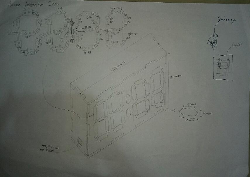
The Project Design
The design of the clock project came from the internet. However, the designs I saw are mostly 3D printed and they use a lot of LEDs. What I've done different is that I lasercut 96% of the design and I made the design smaller so that it uses only 30 Neopixels while other designs use 60 neopixels or more. What I have also done different is that I have used wood instead of acrylic to give the clock design a twist.
How to construct this project
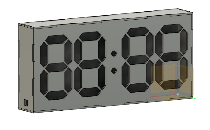
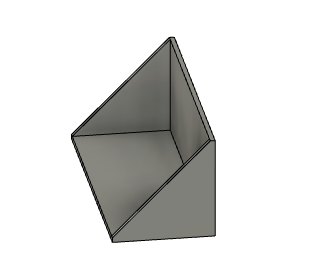
Design a parametric box on Fusion. For the parametric box, ensure you include a hole for the USB cable and also design one segment for the seven segment, and copy and paste the segment four times.Then extrude the segments to make 4 seven segment holes. Then, include two holes in the middle for it to resemble an actual digital clock.
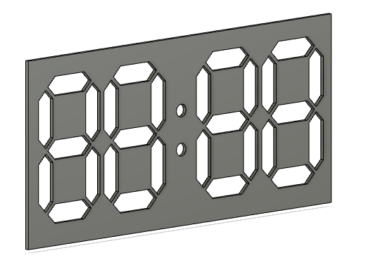
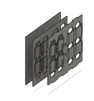
For the inside, I made a 2nd lasercut print of the design of the clock digits. The purpose of the this piece is to block out LED light that will wrongly shine on another digit. With this piece, the led lights will reflect clearly and wont shine on other pieces.
Then, I made another piece which is just a rectangle. The purpose of this piece is to be a board to align and place the LEDS. On this board, you can draw the outline of where the lights will be placed, and then tape the Neopixels on the proper spot, and then solder everything together
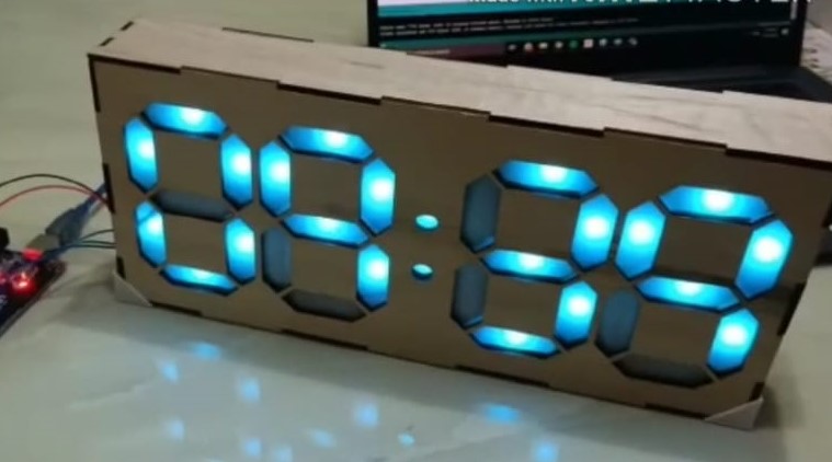
This is what the inside will look like, as well as the outer part of the display
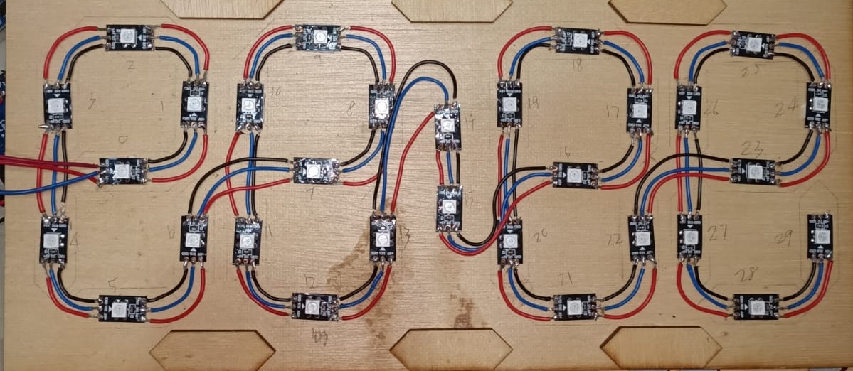
The items I had were 30 Neopixels, a RTC, an Arduino board and wires. I cut the Neopixel strip into 30 seperate Neopixel lights. Then, I used double sided tape and taped each neopixel onto the empty board, according to where the lights are needed. This is how the electronics were wired.
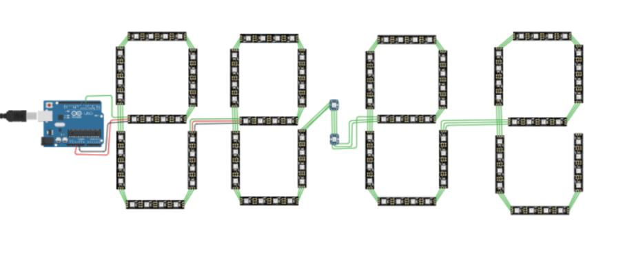
However, instead of 4 Neopixels per segment, I used 1 neopixel per segment. Make sure that the direction of the neopixel follows the direction of the wire, away from the arduino board.
Wiring
Then, solder all the neopixels together. After that, solder the ground wire of the arduino to the ground of the Neopixel and RTC. Also, solder the 5V wire of the arduino to the 5V of the Neopixel and RTC. Connect the RTC's SDA and SCL wire to the Arduino and connect the Neopixel's input wire to input 6 of the arduino board. This will be the wiring for the clock.
This part is the most complicated part of the entire project and you can choose to find available codes online. What I have done is that I took a code from the internet and changed the code so that it fits my design of one neopixel per segment. This is the link to the code that I found from the internet.
https://www.instructables.com/id/RGB-7-segment-Display-Clock-With-WS2812B/?linkId=80091578Finally, I decided to 3D print 2 pieces of corner holders to make sure that the box will never fall apart easily. This piece will be placed on the bottom corners of the clock box.
Original Design Files and Code
The box of the Clock that had been laser cutted
The Clock Holder piece that had been 3D printed
The Code used for the project
What was completed, what was successful, what needs more work
What Was Completed
What Was Completed
I managed to make a functional clock with Neopixels that changes color.
What was successful
The design and the lights of the clock makes the project look very attractive and simple. The project works like a normal clock and is simple.
What needs more work
What needs more work is that a button could have been added to make the clock switch on and off at any time. The code of the project is in 24h format. Hence, it would be better if I could change it such that you can choose between a 12-hour format and a 24-hour format. What went wrong is that I was careless and did not measure the length of the arduino board which resulted in it not fitting in the project.
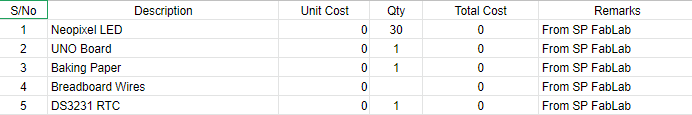
Bill Of Materials